Two timing jerks are bad, but timing two jerks can be surprisingly useful.
Background
One of the annoying things about professional life is that you are often not allowed to talk about what you do due to non-disclosure agreements etc. One minor perk about some government jobs is that often what you do ends up being in the public record anyway and it is now no secret that I have often needed to ‘witness tests’. While most of the time witnessing is non-intrusive and you’re just making sure they’re following the procedure, sometimes you feel the urge to sanity check some things by carrying your own tape measures, laser measures, thermal cameras and the now trusty smartphone that can double up as a stop watch etc (this is my excuse for why I have a thermal camera in my pocket and I’m sticking with it).
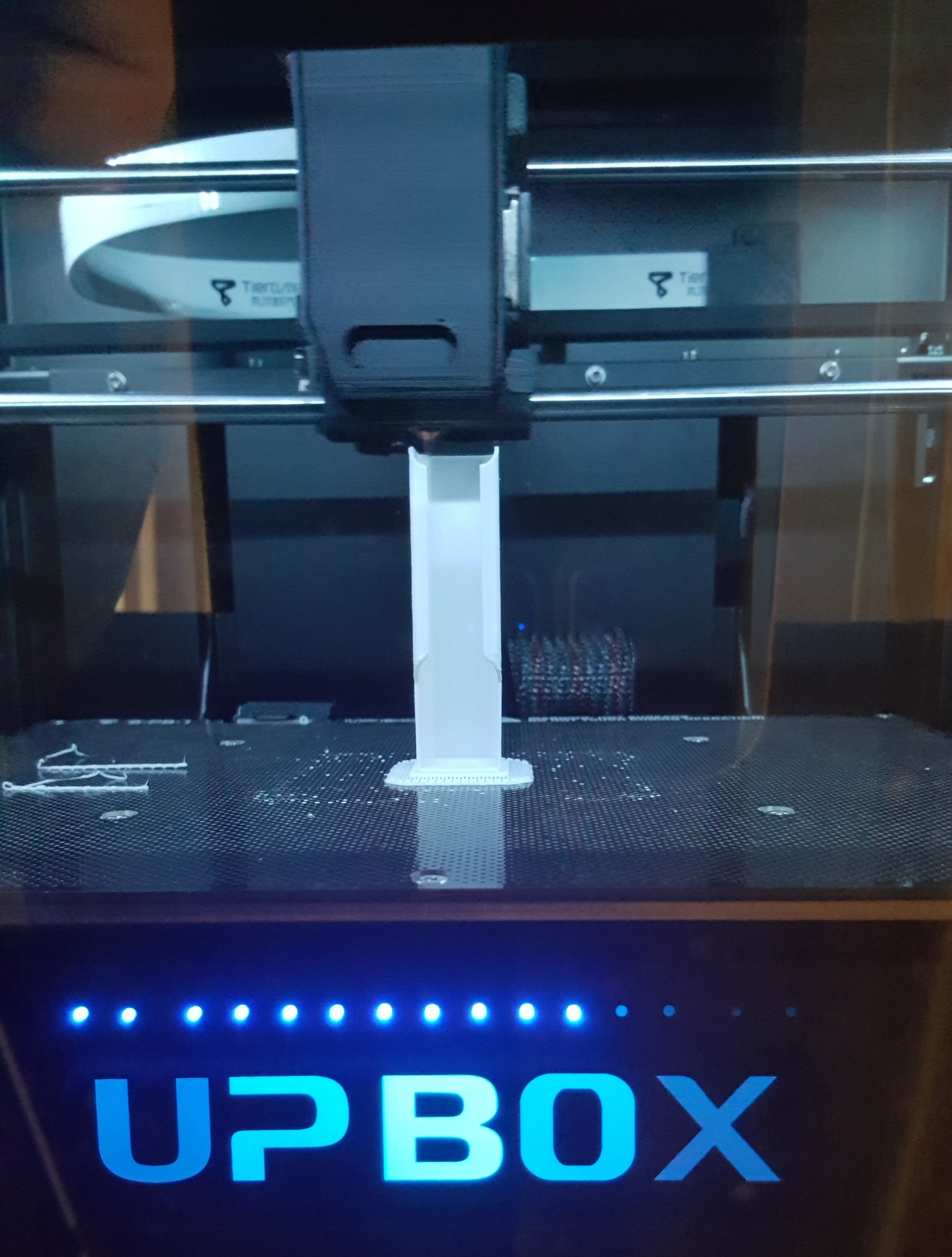
So on one particular trip in Spain, I brought along in my bag a M5Capsule by M5Stack thinking that I would be able to use it as part of my test witnessing. The naivety at the time was that I would have time on the plane and/or in between tests to prepare the software for it, the reality is that flying economy for work is painful and trying to get a laptop out for work is impossible and so is the concept of ‘in-between tests’ when working to a tight schedule. The idea and desire at the time was that anything with movement, can probably be timed by monitoring accelerometer data. Whether it be the opening/closing of a door, the cycle time of a windscreen wiper, or even just validating the time from start of braking to complete stop.
Looping back to the trusty smartphone, there’s a wonderful app called Phyphox available for both Android and Apple that allows you to use your phones suite of sensors to do experiments and it kind of works in many of the cases so check it out! There are other cases though, that either the phone is too heavy (to strap to a windscreen wiper…) or too valuable (to potentially drop/damage) and the M5Capsule idea seems practical again.
Concept
So the concept is to be able to strap/stick/attach the light weight (~19g) to something and measure the time between two accelerometer events such as sudden jerks or a change in direction. As the device could be mounted in any orientation, and the accelerations would be vastly different for different scenarios, there’s no easy threshold trigger that one would be able to set for an event. I opted for plotting the acceleration over time, and allowing the user to select any two points of the waveform to mark the time (hence… ‘ChronoMark’) and calculate the time difference.
The accelerometer data will be transmitted to a phone/tablet/computer via Bluetooth, and displayed on a Web HTML UI without the need for any apps/software to be installed. The selection of Bluetooth is to streamline the user experience, to avoid potential loss of internet connection for the user device and avoid the need to type in a potentially horrid URL with weird IP addresses etc. It also gives me a perfect change to learn about Web BT (and you’d see many more Web BT examples coming soon…)
Software
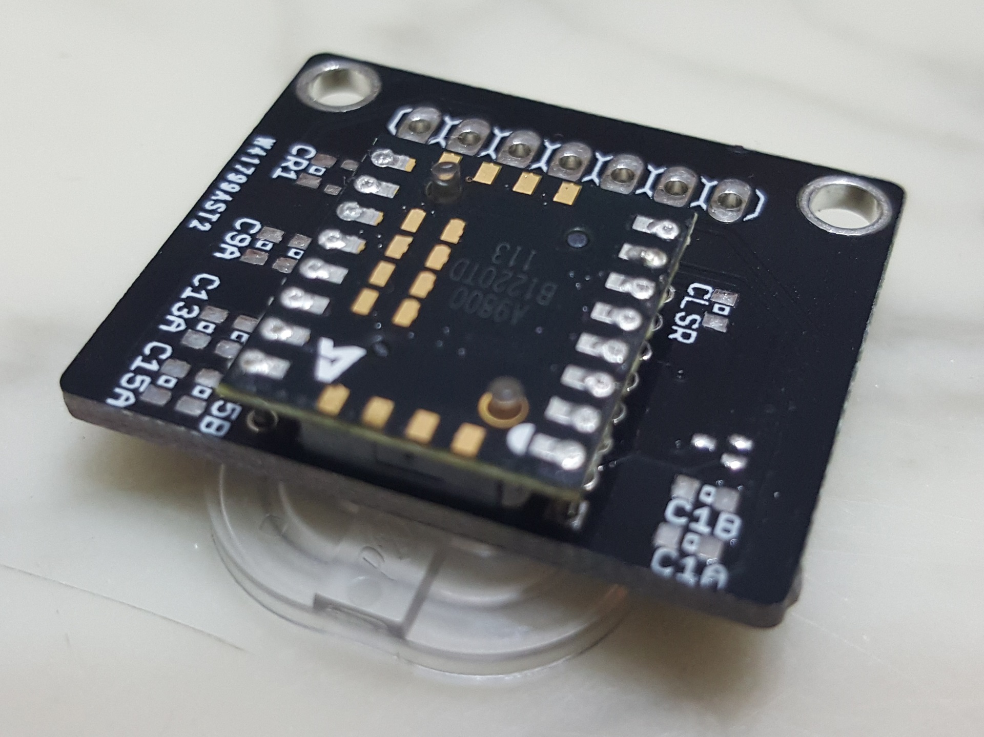
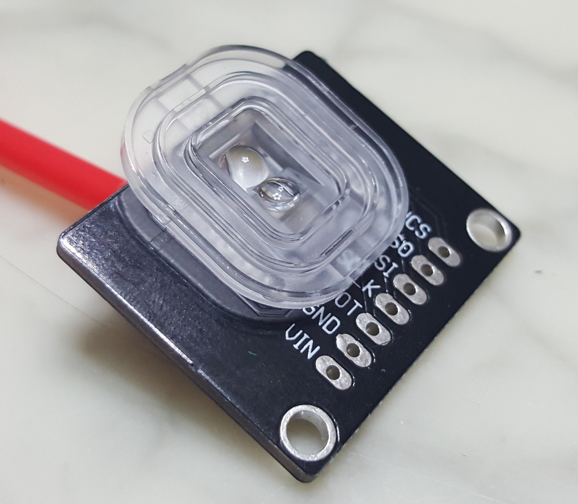
The hardware is purely the M5Capsule module (or similar modules such as M5StickC etc), without any additional components which leaves us with two software components. The firmware, and the UI.
The firmware
The ESP32S3 firmware was unashamedly mostly generated by Google’s Gemini AI, again another opportunity for me to learn about and evaluate new technologies in a ‘non-production’ environment. It was indeed pretty easy and quick to generate the initial framework and a demo application but there were some hiccups along the way.
I often tend to feature creep myself and wanted to add connection / disconnection tones to the device whenever Bluetooth is connected / disconnected as feedback to the user. This is where Gemini AI hallucinated with plausible but bad functions and code, not being helpful in reverting to previous working code, and not being able to take in manual edits without odd edits in sometimes random places. I also gave up my quest for a ‘Windows Bootup/Logon’ sound when I realised it’d be impossible given the tiny buzzer of the M5Capsule.
Gemini also initially used a pattern where a formatted string was being use to send the accelerometer data, which could be very long and had to be parsed at the other end. It also used rather arbitrary ‘random’ service and characteristic UUIDs. It was relatively easy again to coax it to use a binary octet pattern for the data transfer, where it brilliantly coded all the auxiliary functions such as checksum creation/checking on both ends. Similarly, I prompted it to use the UUIDs of the ‘Nordic UART Service‘ as I thought emulating it would make future maintenance easier instead of needing to track a bazillion bespoke UUIDs for each new project.
If you want to use my Web UI, you can make your own firmware with the Nordic UART Service and use the following data structure. The Web UI does have a filter on devices called ‘ChronoMark’. This table is also generated by Gemini AI!
| Field | Offset (Bytes) | Size (Bytes) | Data Type | Value / Description |
| Header | 0 | 2 | uint16_t | A constant value of 0xBEEF to mark the start of a packet. |
| Length | 2 | 1 | uint8_t | The length of the following Type and Payload fields. (Value is 13). |
| Type | 3 | 1 | uint8_t | The type of data in the payload. 0x01 for accelerometer data. |
| Payload | 4 | 12 | float[3] | Three 4-byte floating-point numbers for the X, Y, and Z axes. |
| Checksum | 16 | 2 | uint16_t | A 16-bit sum of all bytes in the Type and Payload fields for error checking. |
| Total | – | 18 | – |
The firmware in the end is around 100 lines of code, that sends the 3-axis accelerometer data approximately every 20ms (it is actually slightly longer, it is just a 20ms delay between cycles).
Web UI
The Web UI is intended to be a simple webpage with a graph where the user can select two marks and calculate the time difference. One of the early working prototypes had the following look –

While Gemini generated the initial example relatively quickly, and I had a working concept within say an hour, it took literal days (24 hours+ at a guess) to fine-tune and finesse the feature set and the arrangement of the UI (the fighting with Gemini for the tunes in the firmware took a few hours too…). A good chunk of that time was also fighting with Gemini, where it would make the oddest mistakes, revert to previous errors, make random edits and quite often outright ‘lie’ in its responses. I put up with it because half the exercise is to try out and explore these new technologies. While on the AI rant, both ChatGPT and Gemini are horrible in generating SVGs and things like favicons etc are much better handled by ChatGPT with Gemini outright unable to do it.

Two external libraries are used in the Web UI, ChartJS with the date and annotation plugins and html2canvas. ChartJS is used to draw the chart obviously, and the initial Gemini code did indeed plot the data but had odd glitches with lines jumping to different places and constant rescaling. Again this was an exercise in fighting with Gemini mostly, with me giving up at times and intervening with manual code edits. I wanted the graph to always have the latest data point on the right hand side, with a fixed x-scale. I ended up changing the ‘x-scale’ to be an index of data points, and the graph to be drawing from a rolling buffer being fed by the M5Capsule. The x-scale is also limited for performance reasons, with 500 data points or around 10 s of data being the default. This is adjustable by a slider bar to between 4 s 20 s of data.
Each datapoint as it is received from the M5Capsule is timestamped by the Web application, on the assumption of negligible or consistent latency. It is this timestamp that is used for calculation. This feature, in addition to a pause/’Stop Plotting’ feature on the UI, allows for data points to be shown on the graph that can be a long time apart where the user can pause during ‘dull periods’ of inactivity. The catch is of course, knowing when to resume/’Start Plotting’ again such that the event of interest is captured on the graph. Below is an example where the interval is much greater than the normal graph limits, discontinuities where the plotting is paused is shown with dashed yellow lines.

The selection of the markers simply alternates between Marker 1 and Marker 2. I tried to think of a better way to do this but gave up as this one works and is relatively easy to manage.
A share button shares the entire screen via html2canvas along with text on supported devices.
Fullscreen was added so the Web App can utilise the full screen on a tablet device, especially when ‘added to the home page’ with Chrome.
Day & night modes for light and dark palettes was also added after I included it in another app and wanted some standardisation across these new apps.
Example applications over the school holidays
Bumps in the race track…
Hastily taped to the side of a Tamiya Mini 4WD track to see if lap times can be measured by passing bumps… yes it can. 4s is a bit slow but the batteries were flat 🙂

Calculating ‘g’ with a pendulum…
Kids school holiday science experiment to calculate the value of ‘g’. We first tried using a USB cable but either the weight or the stiffness gave poor results. Using a thin ‘invisible string’ gave us results approximately 1% away from the theoretical expected result!


Calculating time taken to fall…
We also did another school holiday experiment to use the equations of motion to calculate how long it would take an object to fall from a particular height, and validating it with the ChronoMark – worked perfectly too… until I realised equations of motion physics isn’t really for primary school kids…
Just watching accelerations in the car…
No timing, but the kids seem relatively amused to watch the accelerations in the car whilst driving.
Source / Sauce
Well I just realised I can’t upload it here and I’m too lazy to set up a project on Gitxxx, does anyone actually want it?
This post has been in draft for some weeks now, leave a comment if you want more info or really want the source 🙂 Coming next is reverse engineering some Bluetooth gadgets!
