Physical reverse engineering often involves 3D scanners and other similar technologies to capture the shape and form of the original object and may require equipment not available to the typical student or young engineer. In this short post, I’ll briefly outline the workflow of designing an ergonomic trackball prototype using approximately $4 worth of toys and no special equipment.
Background
A significant portion of my working time is spent in front of a computer, operating a computer. So it makes sense that the input devices I use should minimise strain on my body and the risks of RSI, and one of the ‘non-standard’ pieces of equipment I favour is a trackball rather than a ‘traditional’ mouse. You can Google up the benefits of a trackball (or a vertical mouse) over a typical mouse, but there is another problem many of us will face – commercial products are typically designed around the ‘average person’, and more often than not, you are not all that average.
Ergonomics for me, myself, and I
Well I fall in the ‘more often than not bucket’ and definitely am not your average human. I have relatively small hands and ‘ergonomic’ trackballs/mice available on the market simply do not quite fit my hands perfectly, and hence my desire to begin a quest to build my own.
Getting the shape of my hand…
Enter the toy! Playfoam!
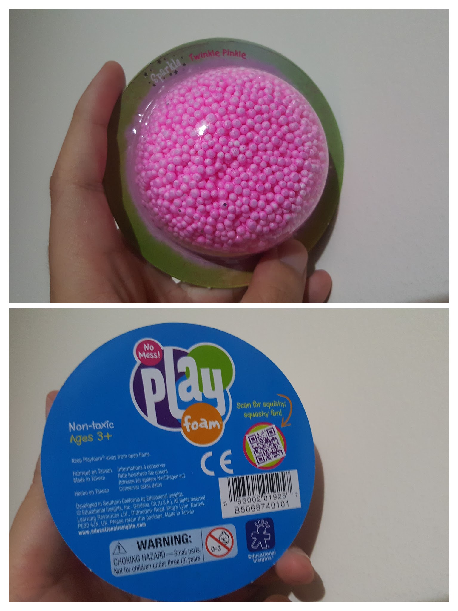
The concept of Playfoam is similar to that of play dough where the material is pliable and can be kneaded or formed into shapes for the young inquisitive mind. However, Playfoam has significant advantages over play dough for this application in that Playfoam is :
- Doesn’t leave a mess everywhere. Even though the pellets are sticky to themselves, there is no residue left over on your hands or anything else you use to shape it.
- Is much softer and pliable! This is the primary benefit in that it doesn’t require the same amount of force you need to form play dough, but rather it just forms into shape.
- Has a natural resultant ‘texture’ that makes getting it into computer format much easier… see later….
- Reusable and won’t dry out.
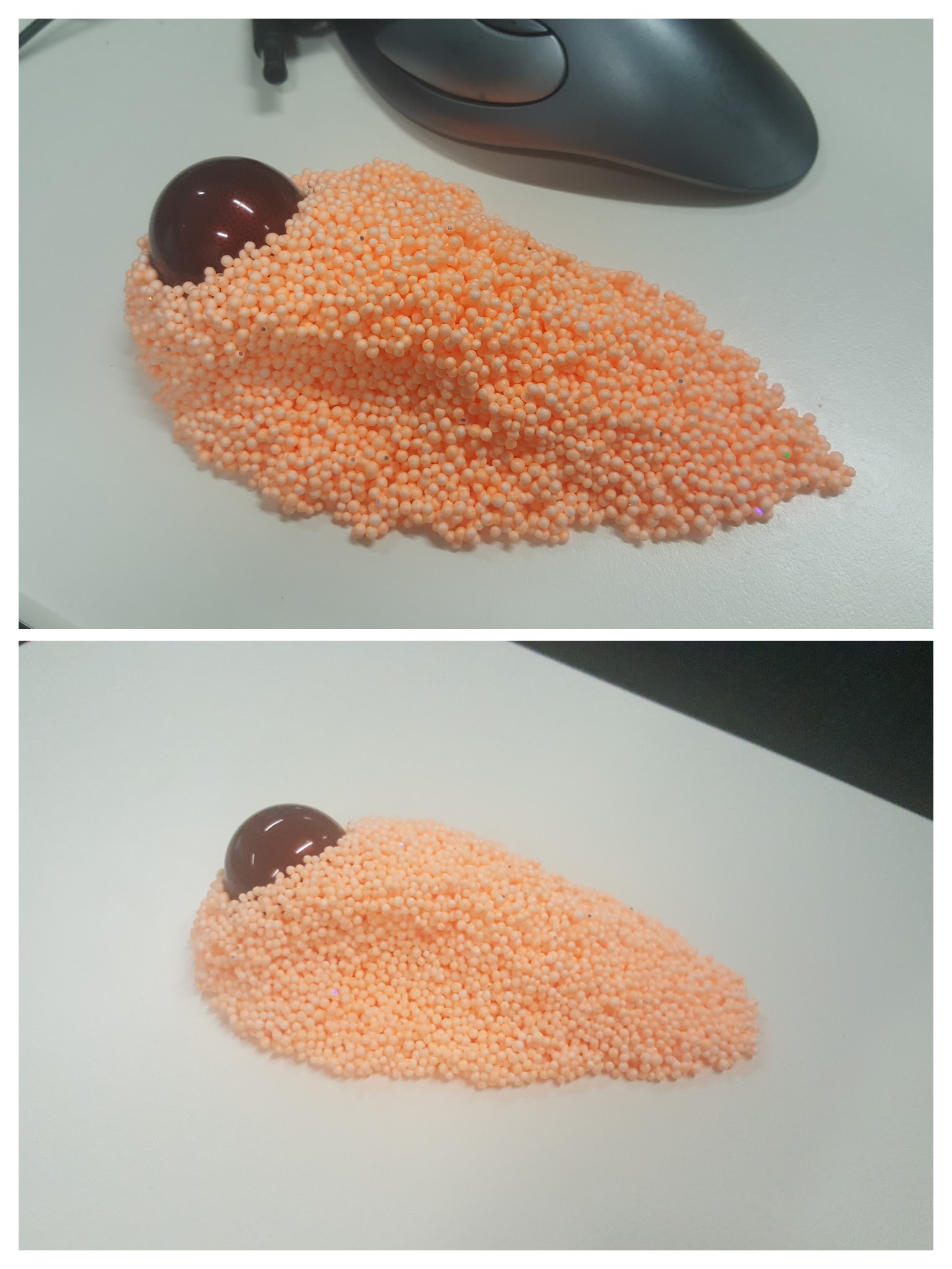
Getting the shape I wanted was simply a matter of grabbing a bunch of the stuff (2 blister packs worth) and making it feel right in my hand as if I was holding and using my ideal trackball. I borrowed a ball from a ‘Logitech Trackman Marble’ to use as a guide on where the ball would be if it was an actual trackball. Sometimes, I had to rearrange some excess material from places of the model to back fill some visible gaps or to stuff into crevices where my hand needed additional support.
Getting the shape into a computer…
‘Scanning’ the shape into the compute is a rather straight forward exercise. I used photogrammetry as I first experimented with many years ago with Autodesk Catch but software moves on and as Photofly morphed into Catch, Catch has been morphed into Autodesk ReMake. The process however is still the same, you take a series of photos angled around the model and load into the program to calculate a 3D model. I didn’t bother with a dedicated camera at all, and simply used the ‘Pro’ mode on my Android phone and used a fixed manual focus for all photos per my experience from ~6 years ago.
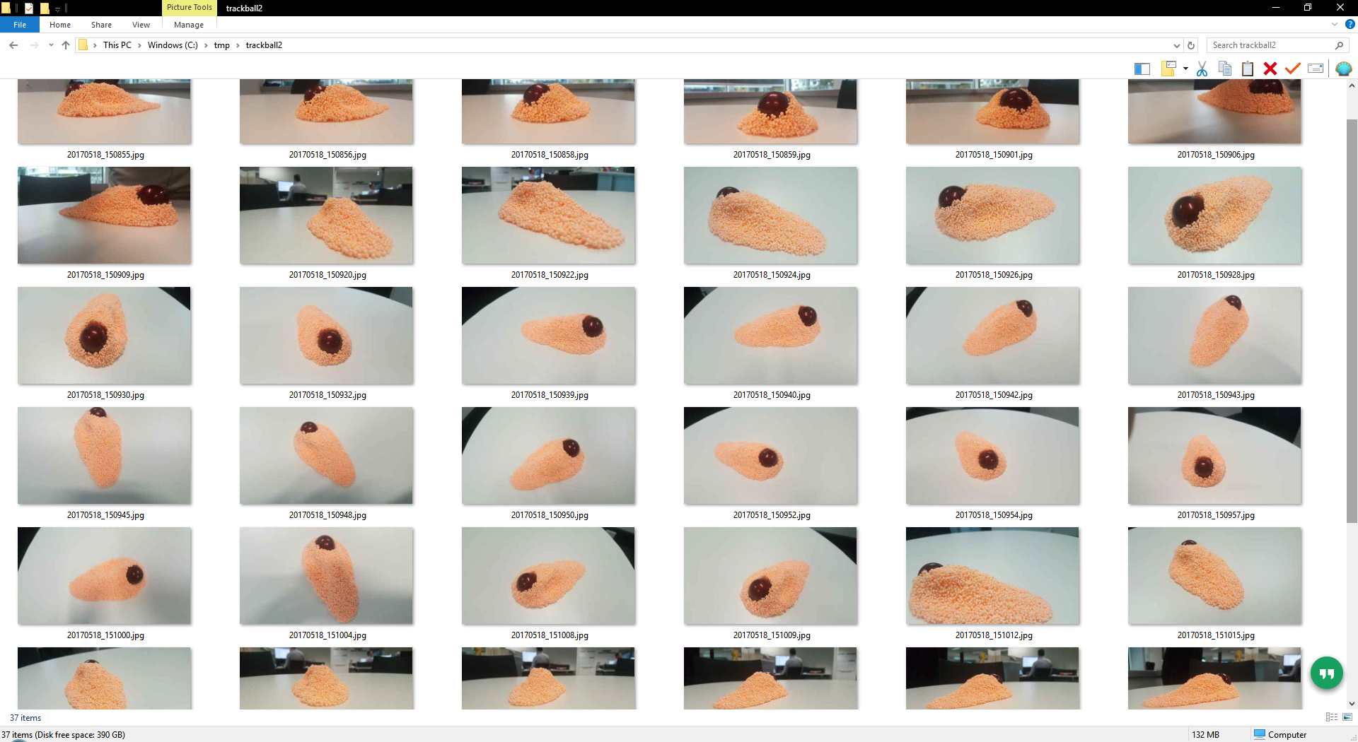
In total, I took 37 photos as pictured above. Another tip is to remember to take photos from a variety of angles, enough to capture the shape of the object and definitely photos from low angles. Photogrammetry struggles with smooth shiny surfaces as it is difficult to match two points in separate photos together if there are no unique features, this is where the texture of the Playfoam balls help get an easy result.
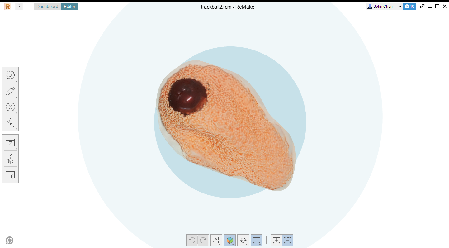
ReMake only works locally if you have a Nvidia graphics card, but there’s always the ‘cloud’ option which is what I used. The model came back in 15-30 minutes after uploading and was good in all areas except the smooth ball which turned out like an alien blob. The model was still bumpy and weird, but good enough!
One thing I forgot to do but should be a lesson learnt, is to put a small ruler or something of known dimensions in the view to be able to scale your model. I made do with the ball which I knew to be 40mm, but it would have been nice to scale off something flat (ReMake lets you measure off two points anywhere within the model).
Getting the weird shape into something usable…
ReMake has the lovely and awesome feature of being able to export into a variety of formats, and conveniently within the Autodesk family of free for hobbyist tools is Fusion 360 (I swear this isn’t an Autodesk ad…).
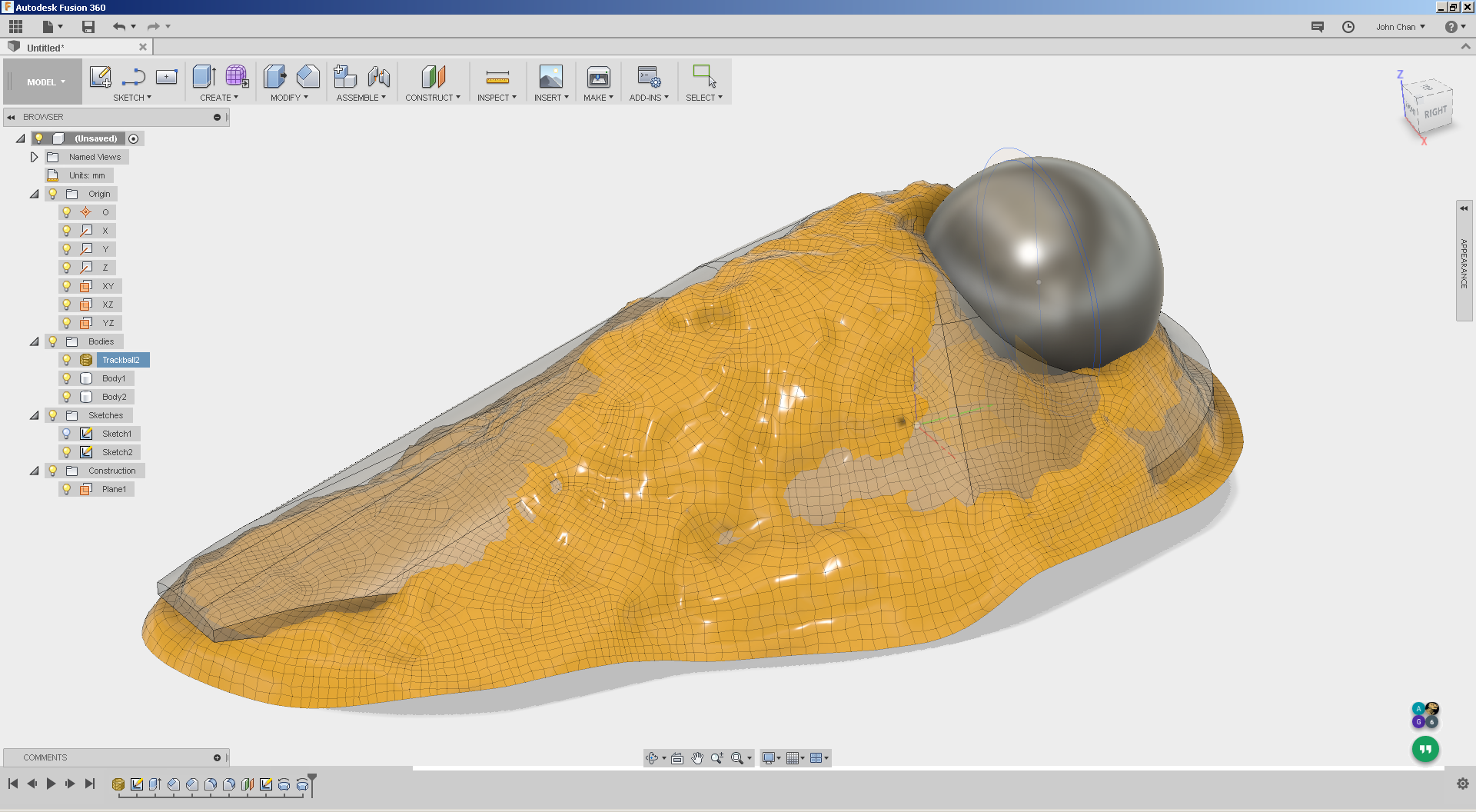
Importing into Fusion 360 is as trivial as ‘Insert Mesh’ and I had a rough 3D model within 15 minutes that ‘almost’ matched the shape of the imported mesh. The trick here in this process is to either make the solid being worked with translucent (50% opacity for example) or the imported mesh to be translucent. This lets you see how close you are with your featured 3D model with your target shape. The picture above shows the imported mesh after being imported in ‘low quality’ and a grey solid modelled using simple features. I dislike sculpting even for this application, and you can see in the feature tree above I had only used so far one extrude, one revolve, and two each of fillets and chamfers for this model (the other revolve is the ball, which technically isn’t part of the what I need).
Validating the shape…
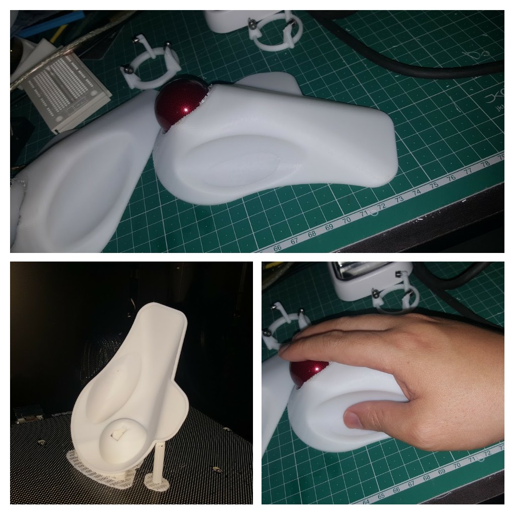
This is where I go ‘oopsies’ and realised that part of my workflow does include the use of special equipment, an Up! Box 3D printer… again not an ad, but tell the guy Madox sent ya 😉
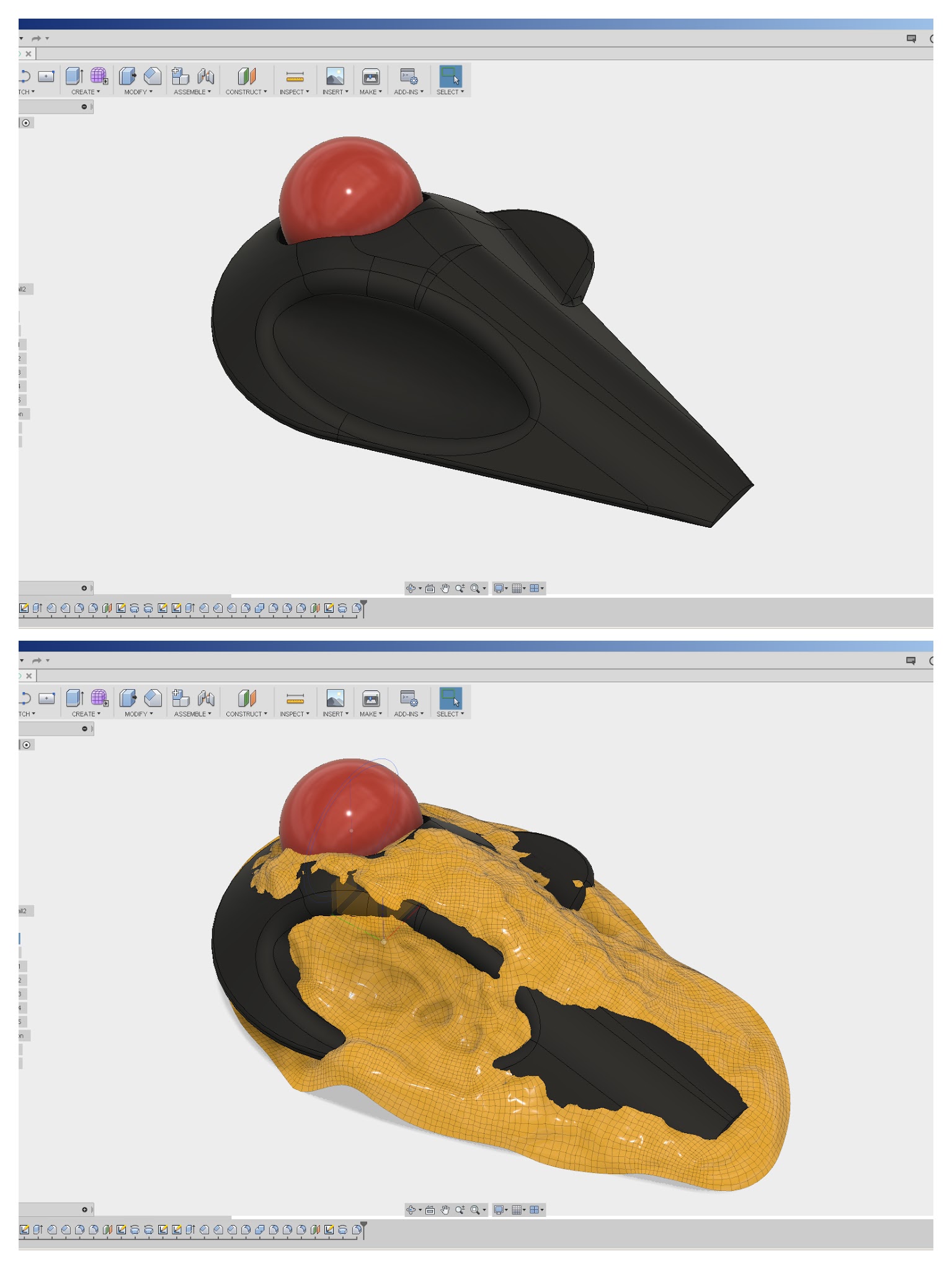
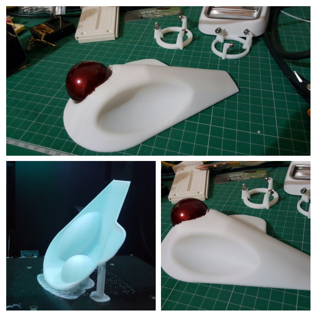
I suppose I could argue the prototype design was complete prior to this step, but having something you can put in your hand to validate is very very nice. Having the physical print (with yet a different donor trackball) to try with my hand made me go ‘meh…this isn’t right…’, that huge mismatch with the mesh should have told me something!
I quickly remodelled the casing and printed it again…yet I still didn’t see the obvious ‘ITS NOT MATCHING THE MESH MATE!’ glaring at me in the screenshot below.
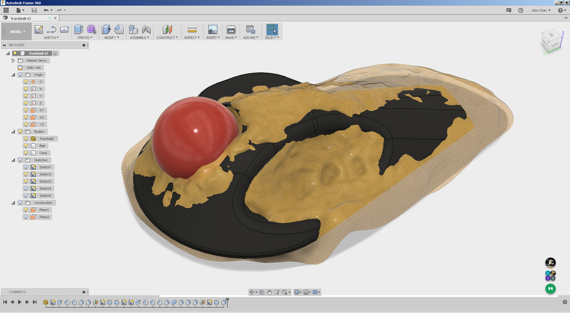
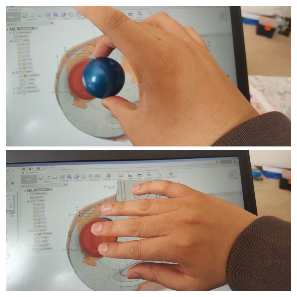
Third time lucky… and on-screen validation
While printing doesn’t cost much, printing two ‘not quite right’ casings was annoying me. Yes that is the point of having a 3D printer, to make mistakes more quickly, but it doesn’t mean I have to like making them.
Then it occurred to me that I could check rough positioning of button placements etc on the screen! A donor 40 mm Kensington trackball was borrowed to calibrate the on-screen display of the CAD model, and I simply placed my hand on the screen to get a rough appreciation that I’ve finally got the buttons in the right place.

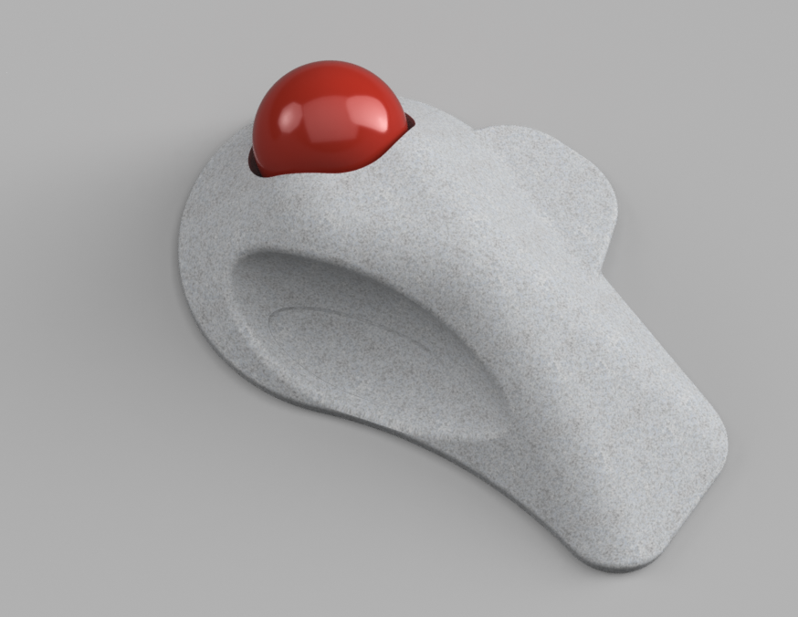
The final fitting confirms the form, shape and placement of the buttons. Yay… now I just have to wait for the electronics to arrive in the mail and onto the next step. Less 3D printing time, uploading and cloud processing time, the actual design effort took roughly an hour and demonstrates how easily a simple child’s toy can be used in an engineering context.
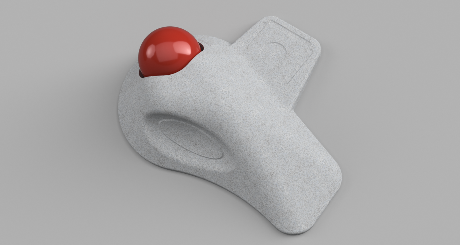
Once I get the electronics, there will probably be more tweaking to be done to the model to fit the items inside but I consider the physical form to be ‘almost complete’ for now. The observative amongst you would have noticed the new ‘wing’ in the final render where my little finger is… let’s just say I’m prone to scope creeping my projects… *cough it might be provision for a 3D gesture controller*
If there is interest, I’ll write up on the electronics design too…
I would LOVE to see more on this. You’ve given me some great ideas and have learned a lot from this post. I’d appreciate any feedback and advice you can give regarding my gaming trackball. My aim is to design a custom housing as you have, and perhaps add the ADNS9800 sensor.
https://www.reddit.com/r/Trackballs/comments/4wbodg/id_like_to_share_my_new_gaming_trackball_im/
Fantastic work on your trackball sir!
I am actually waiting for a bunch of ADNS-9800 sensors to arrive. I will be experimenting with the bearing arrangement first (waiting for some silicon nitride balls and ball transfer units to come… Did you see a roller bearing rig in the background of some photos?), then laser sensor positioning, then wireless firmware, then different button types. Will be leaving the 3D gesture control last 🙂