ChronoMark – The art of timing two jerks

Two timing jerks are bad, but timing two jerks can be surprisingly useful.

Background

One of the annoying things about professional life is that you are often not allowed to talk about what you do due to non-disclosure agreements etc. One minor perk about some government jobs is that often what you do ends up being in the public record anyway and it is now no secret that I have often needed to ‘witness tests’. While most of the time witnessing is non-intrusive and you’re just making sure they’re following the procedure, sometimes you feel the urge to sanity check some things by carrying your own tape measures, laser measures, thermal cameras and the now trusty smartphone that can double up as a stop watch etc (this is my excuse for why I have a thermal camera in my pocket and I’m sticking with it).

So on one particular trip in Spain, I brought along in my bag a M5Capsule by M5Stack thinking that I would be able to use it as part of my test witnessing. The naivety at the time was that I would have time on the plane and/or in between tests to prepare the software for it, the reality is that flying economy for work is painful and trying to get a laptop out for work is impossible and so is the concept of ‘in-between tests’ when working to a tight schedule. The idea and desire at the time was that anything with movement, can probably be timed by monitoring accelerometer data. Whether it be the opening/closing of a door, the cycle time of a windscreen wiper, or even just validating the time from start of braking to complete stop.

Looping back to the trusty smartphone, there’s a wonderful app called Phyphox available for both Android and Apple that allows you to use your phones suite of sensors to do experiments and it kind of works in many of the cases so check it out! There are other cases though, that either the phone is too heavy (to strap to a windscreen wiper…) or too valuable (to potentially drop/damage) and the M5Capsule idea seems practical again.

Concept

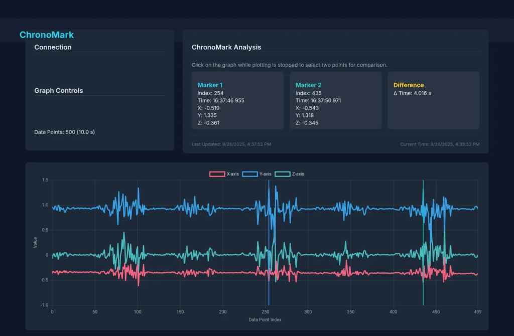
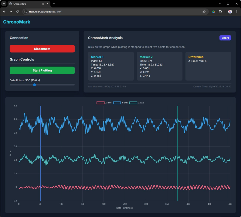
So the concept is to be able to strap/stick/attach the light weight (~19g) to something and measure the time between two accelerometer events such as sudden jerks or a change in direction. As the device could be mounted in any orientation, and the accelerations would be vastly different for different scenarios, there’s no easy threshold trigger that one would be able to set for an event. I opted for plotting the acceleration over time, and allowing the user to select any two points of the waveform to mark the time (hence… ‘ChronoMark’) and calculate the time difference.

The accelerometer data will be transmitted to a phone/tablet/computer via Bluetooth, and displayed on a Web HTML UI without the need for any apps/software to be installed. The selection of Bluetooth is to streamline the user experience, to avoid potential loss of internet connection for the user device and avoid the need to type in a potentially horrid URL with weird IP addresses etc. It also gives me a perfect change to learn about Web BT (and you’d see many more Web BT examples coming soon…)

Software

The hardware is purely the M5Capsule module (or similar modules such as M5StickC etc), without any additional components which leaves us with two software components. The firmware, and the UI.

The firmware

The ESP32S3 firmware was unashamedly mostly generated by Google’s Gemini AI, again another opportunity for me to learn about and evaluate new technologies in a ‘non-production’ environment. It was indeed pretty easy and quick to generate the initial framework and a demo application but there were some hiccups along the way.

I often tend to feature creep myself and wanted to add connection / disconnection tones to the device whenever Bluetooth is connected / disconnected as feedback to the user. This is where Gemini AI hallucinated with plausible but bad functions and code, not being helpful in reverting to previous working code, and not being able to take in manual edits without odd edits in sometimes random places. I also gave up my quest for a ‘Windows Bootup/Logon’ sound when I realised it’d be impossible given the tiny buzzer of the M5Capsule.

Gemini also initially used a pattern where a formatted string was being use to send the accelerometer data, which could be very long and had to be parsed at the other end. It also used rather arbitrary ‘random’ service and characteristic UUIDs. It was relatively easy again to coax it to use a binary octet pattern for the data transfer, where it brilliantly coded all the auxiliary functions such as checksum creation/checking on both ends. Similarly, I prompted it to use the UUIDs of the ‘Nordic UART Service‘ as I thought emulating it would make future maintenance easier instead of needing to track a bazillion bespoke UUIDs for each new project.

If you want to use my Web UI, you can make your own firmware with the Nordic UART Service and use the following data structure. The Web UI does have a filter on devices called ‘ChronoMark’. This table is also generated by Gemini AI!

FieldOffset (Bytes)Size (Bytes)Data TypeValue / Description
Header02uint16_tA constant value of 0xBEEF to mark the start of a packet.
Length21uint8_tThe length of the following Type and Payload fields. (Value is 13).
Type31uint8_tThe type of data in the payload. 0x01 for accelerometer data.
Payload412float[3]Three 4-byte floating-point numbers for the X, Y, and Z axes.
Checksum162uint16_tA 16-bit sum of all bytes in the Type and Payload fields for error checking.
Total18

The firmware in the end is around 100 lines of code, that sends the 3-axis accelerometer data approximately every 20ms (it is actually slightly longer, it is just a 20ms delay between cycles).

Web UI

The Web UI is intended to be a simple webpage with a graph where the user can select two marks and calculate the time difference. One of the early working prototypes had the following look –
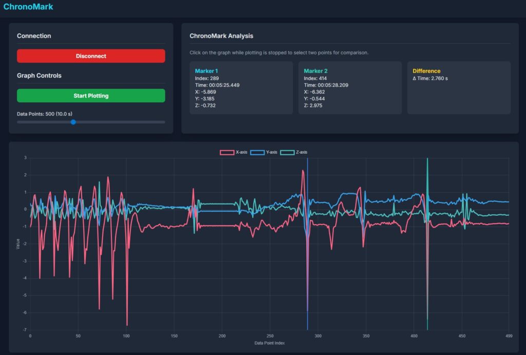
Early UI

While Gemini generated the initial example relatively quickly, and I had a working concept within say an hour, it took literal days (24 hours+ at a guess) to fine-tune and finesse the feature set and the arrangement of the UI (the fighting with Gemini for the tunes in the firmware took a few hours too…). A good chunk of that time was also fighting with Gemini, where it would make the oddest mistakes, revert to previous errors, make random edits and quite often outright ‘lie’ in its responses. I put up with it because half the exercise is to try out and explore these new technologies. While on the AI rant, both ChatGPT and Gemini are horrible in generating SVGs and things like favicons etc are much better handled by ChatGPT with Gemini outright unable to do it.

Two external libraries are used in the Web UI, ChartJS with the date and annotation plugins and html2canvas. ChartJS is used to draw the chart obviously, and the initial Gemini code did indeed plot the data but had odd glitches with lines jumping to different places and constant rescaling. Again this was an exercise in fighting with Gemini mostly, with me giving up at times and intervening with manual code edits. I wanted the graph to always have the latest data point on the right hand side, with a fixed x-scale. I ended up changing the ‘x-scale’ to be an index of data points, and the graph to be drawing from a rolling buffer being fed by the M5Capsule. The x-scale is also limited for performance reasons, with 500 data points or around 10 s of data being the default. This is adjustable by a slider bar to between 4 s 20 s of data.

Each datapoint as it is received from the M5Capsule is timestamped by the Web application, on the assumption of negligible or consistent latency. It is this timestamp that is used for calculation. This feature, in addition to a pause/’Stop Plotting’ feature on the UI, allows for data points to be shown on the graph that can be a long time apart where the user can pause during ‘dull periods’ of inactivity. The catch is of course, knowing when to resume/’Start Plotting’ again such that the event of interest is captured on the graph. Below is an example where the interval is much greater than the normal graph limits, discontinuities where the plotting is paused is shown with dashed yellow lines.
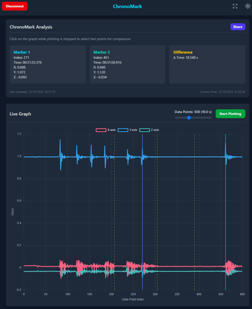
Capturing long intervals between events, discontinuities are shown with a yellow dashed line

The selection of the markers simply alternates between Marker 1 and Marker 2. I tried to think of a better way to do this but gave up as this one works and is relatively easy to manage.

A share button shares the entire screen via html2canvas along with text on supported devices.

Fullscreen was added so the Web App can utilise the full screen on a tablet device, especially when ‘added to the home page’ with Chrome.

Day & night modes for light and dark palettes was also added after I included it in another app and wanted some standardisation across these new apps.

Example applications over the school holidays

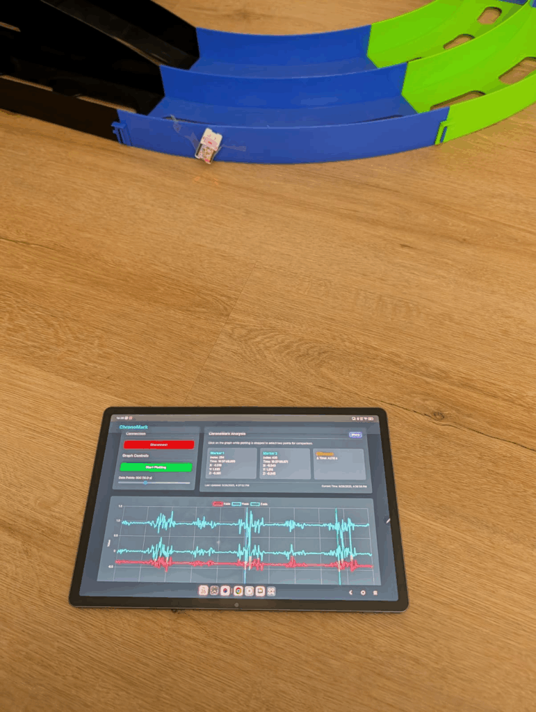
Bumps in the race track…

Hastily taped to the side of a Tamiya Mini 4WD track to see if lap times can be measured by passing bumps… yes it can. 4s is a bit slow but the batteries were flat 🙂
Calculating ‘g’ with a pendulum…

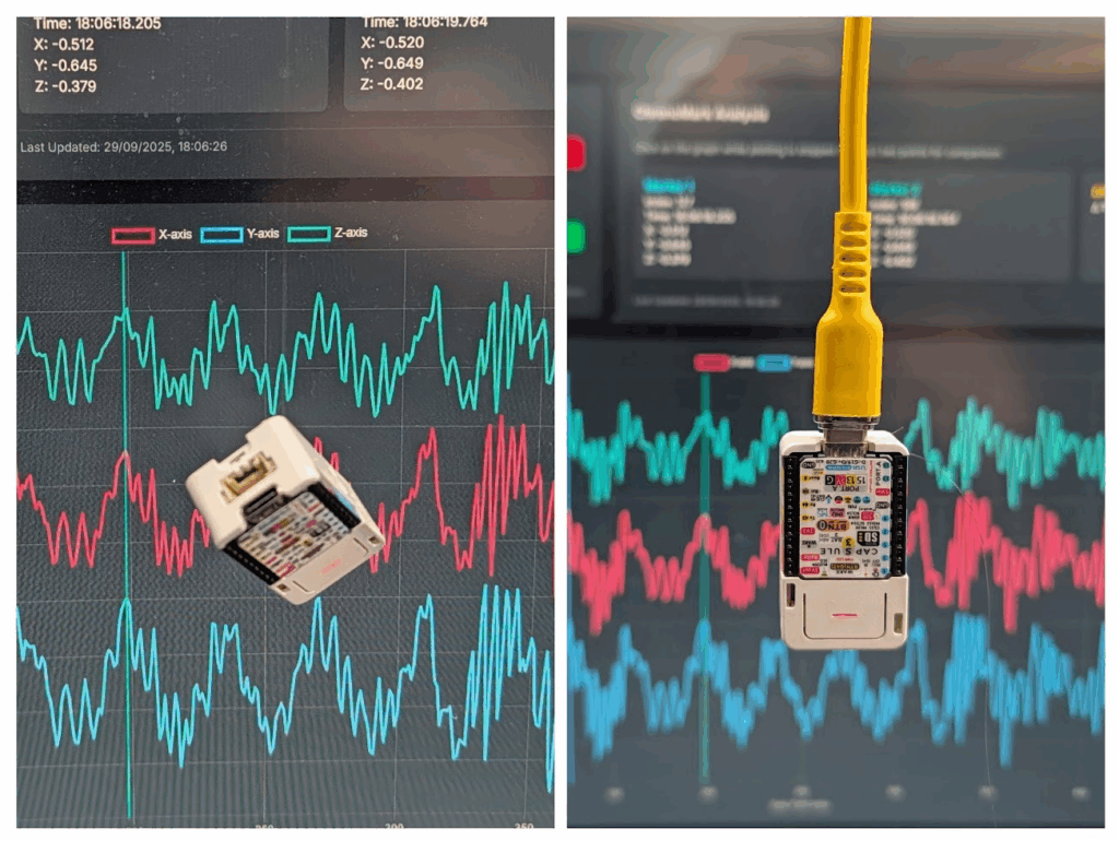
Kids school holiday science experiment to calculate the value of ‘g’. We first tried using a USB cable but either the weight or the stiffness gave poor results. Using a thin ‘invisible string’ gave us results approximately 1% away from the theoretical expected result!
Calculating time taken to fall…

We also did another school holiday experiment to use the equations of motion to calculate how long it would take an object to fall from a particular height, and validating it with the ChronoMark – worked perfectly too… until I realised equations of motion physics isn’t really for primary school kids…

Just watching accelerations in the car…

No timing, but the kids seem relatively amused to watch the accelerations in the car whilst driving.

Source / Sauce

Well I just realised I can’t upload it here and I’m too lazy to set up a project on Gitxxx, does anyone actually want it?

This post has been in draft for some weeks now, leave a comment if you want more info or really want the source 🙂 Coming next is reverse engineering some Bluetooth gadgets!
PCBWay – Yet another PCB service

Everyone seems to be hesitant to try out a new PCB service in fear of the unknown.  Will it be slow? Will it accept my gerbers?  Will it cost $3248945 to ship?

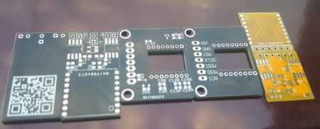
Seeedstudio recently changed their shipping prices and it was like ~$25USD for shipping to Australia – the small drop in prices doesn’t justify that.  So I decided to try PCBWay, $5USD for 10 PCBs which is the same price but they appeared to have a variety of shipping options ranging from DHL to HK Post as well as an ‘e-packet’ option which isn’t advertised on the shipping FAQ.

30 PCBs for $23 USD delivered...
30 PCBs for $23 USD delivered…

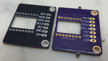
I decided to place some orders to check out the speed of delivery and quality and am pleasantly surprised!  I placed an order on the 7th June with the PCBs arriving on the 23rd June with a total turnaround time of 16 days including shipping to Australia.  As a benchmark comparison, I ordered from OSHPark the same day with their famous free shipping included and it was a nice tie with the purple boards also arriving at the same time.


Thin! 0.6mm Thin!

OSHPark is a great service but is limited in the colour selection and thickness of the PCBs.  PCBWay has a variety of options on colours and thicknesses at no extra cost (still $5 for 10 boards!).

Whilst there is ‘live pricing’ on PCBWay, there is a manual review check that makes the ordering process slightly annoying.  i.e. You get your pricing, upload your gerbers…then…you have to wait for several hours for it to be checked before you can pay and finalise your order.  This contrasts with other places where the responsibility of the visual checks is on you.  e.g. OSHPark clearly showed my internal cut-out was going to work… I had to risk it with PCBWay (and it came out ok!).

PCBWay vs OSHPark

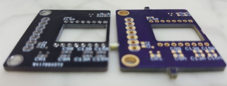
Comparatively, the silkscreen from OSHPark look more representative of the original text on the screen but the more ‘compact’ and bold fonts from PCBWay actually look better to me!

Internal cut-outs are both A-OK

Internal cut-outs worked well from both fabs, though it seems PCBWay uses a smaller bit so the rounding on the corners is less obvious.  Those panelisation tabs on OSHPark are so annoying…

Overall, the boards turned out great but I realise I probably want to redesign some of these boards and make them more compact, ah at least they didn’t cost much.

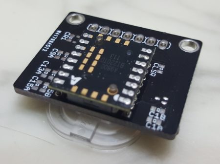
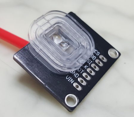
Hey it fits!
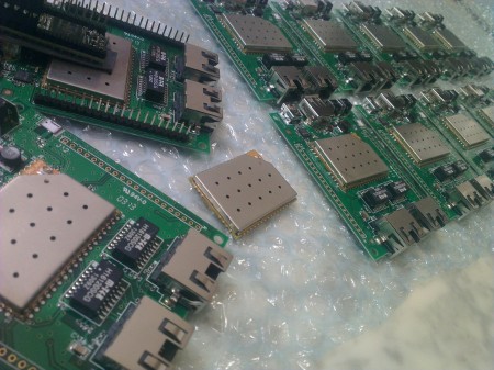
ADNS-9800 laser sensor module… I’m redesigning this board :O


Tribology – DIY Trackball #2

A key design decision I need to make on my way to my DIY trackball is how I would mount/attach the ball.  How the ball interacts with the holder through friction and wear etc falls under the study of ‘tribology‘, which originally read like tribolites to me!

There are various arrangements used by commercial trackballs ranging from fixed synthetic ruby balls (Kensington/Elecom), free rolling zirconium oxide balls (Logitech), and roller bearings (CST).  Which one is best for me?

Considerations for a commercial product vs a DIY trackball may carry different weights, I have to consider ease of assembly/manufacture so I can make the thing and perhaps not so much on longevity if I can replace or maintain it quite readily.

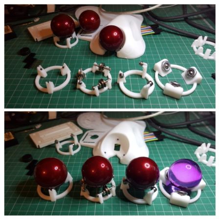
To make my own qualitative assessments, I 3D-printed test rigs with different arrangements to evaluate the ‘feel’ and ‘noise’ of each.

Trackball experiments with my dwindling supply of balls…

In the picture above are 5 arrangements :-

  1. Rear (mounted on a test case) – 3 × fixed silicon nitride 3mm diameter balls.
  2. Left – 3 × loose/free rolling silicon nitride 3mm diameter balls.
  3. Second from left – 3 × 623VV (3 × 12 × 4mm) V-groove bearings.
  4. Second from right – 3 × MR63ZZ (3 × 6 × 2.5mm) bearings
  5. Right – 3 × 8mm ball transfer units.

Qualitative personal opinion wise, the silicon nitride ball setups performed  best to my liking in terms of smoothness.  I had expected the roller bearings to be the noisiest, but the silicon nitride balls sounded louder but much more tolerable – the metal on metal sound was much more annoying even though it is quieter.

The ball transfer unit set-up did not work well at all, and offered significant resistance.  Admittedly these are cheap units, and the grease/oil lubrication that came with them just wouldn’t work as a hand held device.

Between the ‘normal’ roller and the ‘V-groove’ roller which is meant to emulate the design change in CST trackballs, the V-groove performed smoother and more consistently.  Not sure if this is the grade of bearings I had, but there seems to be a consensus out there the new rollers on the CST is an improvement, so it is nice to obtain a consistent result with that.

So it is decided, silicon nitride balls it is!  With the 3D printing of the test rigs, I designed an arrangement that allowed fitment/replacement of the balls directly in the 3D print without the complication of a custom ‘ball transfer unit’ I had intended to make out of  Polycaprolactone (aka Polymorph in Australia).

Next step, electronics, or specifically the laser sensor.  Hopefully the PCBs will arrive this week and I’ll have some time the following week to assemble to do some tests with the sensor vs different balls.

Engineering Design using Children’s Toys

Physical reverse engineering often involves 3D scanners and other similar technologies to capture the shape and form of the original object and may require equipment not available to the typical student or young engineer. In this short post, I’ll briefly outline the workflow of designing an ergonomic trackball prototype using approximately $4 worth of toys and no special equipment.

Background

A significant portion of my working time is spent in front of a computer, operating a computer. So it makes sense that the input devices I use should minimise strain on my body and the risks of RSI, and one of the ‘non-standard’ pieces of equipment I favour is a trackball rather than a ‘traditional’ mouse.  You can Google up the benefits of a trackball (or a vertical mouse) over a typical mouse, but there is another problem many of us will face – commercial products are typically designed around the ‘average person’, and more often than not, you are not all that average.

Ergonomics for me, myself, and I

Well I fall in the ‘more often than not bucket’ and definitely am not your average human.  I have relatively small hands and ‘ergonomic’ trackballs/mice available on the market simply do not quite fit my hands perfectly, and hence my desire to begin a quest to build my own.

Getting the shape of my hand…

Enter the toy!  Playfoam!

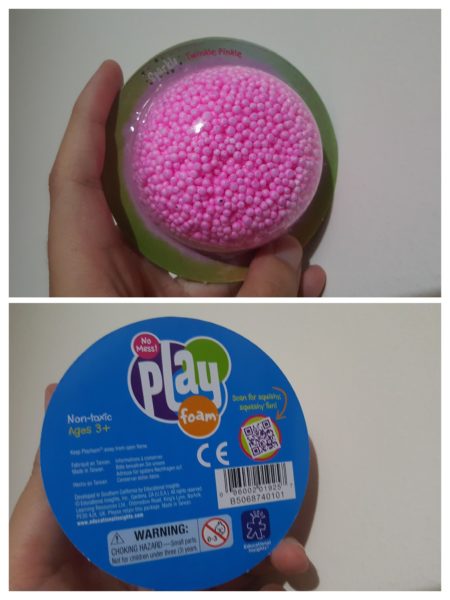
Playfoam! With sparkles to make it more fabulous!

The concept of Playfoam is similar to that of play dough where the material is pliable and can be kneaded or formed into shapes for the young inquisitive mind.  However, Playfoam has significant advantages over play dough for this application in that Playfoam is :

  1. Doesn’t leave a mess everywhere.  Even though the pellets are sticky to themselves, there is no residue left over on your hands or anything else you use to shape it.
  2. Is much softer and pliable!  This is the primary benefit in that it doesn’t require the same amount of force you need to form play dough, but rather it just forms into shape.
  3. Has a natural resultant ‘texture’ that makes getting it into computer format much easier… see later….
  4. Reusable and won’t dry out.

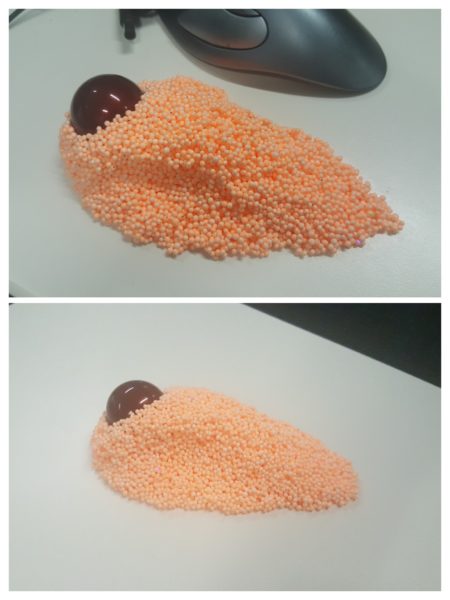
Getting the shape I wanted was simply a matter of grabbing a bunch of the stuff (2 blister packs worth) and making it feel right in my hand as if I was holding and using my ideal trackball.  I borrowed a ball from a ‘Logitech Trackman Marble’ to use as a guide on where the ball would be if it was an actual trackball.  Sometimes, I had to rearrange some excess material from places of the model to back fill some visible gaps or to stuff into crevices where my hand needed additional support.

Trackball in Playfoam, can you see the glitter sparkling?

Getting the shape into a computer…

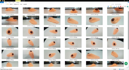
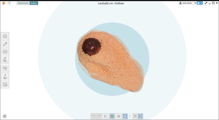
‘Scanning’ the shape into the compute is a rather straight forward exercise.  I used photogrammetry as I first experimented with many years ago with Autodesk Catch but software moves on and as Photofly morphed into Catch, Catch has been morphed into Autodesk ReMake.  The process however is still the same, you take a series of photos angled around the model and load into the program to calculate a 3D model.  I didn’t bother with a dedicated camera at all, and simply used the ‘Pro’ mode on my Android phone and used a fixed manual focus for all photos per my experience from ~6 years ago.

Input photos, note the variety of angles in the photos.

In total, I took 37 photos as pictured above.  Another tip is to remember to take photos from a variety of angles, enough to capture the shape of the object and definitely photos from low angles.  Photogrammetry struggles with smooth shiny surfaces as it is difficult to match two points in separate photos together if there are no unique features, this is where the texture of the Playfoam balls help get an easy result.

Resultant ReMake Model

ReMake only works locally if you have a Nvidia graphics card, but there’s always the ‘cloud’ option which is what I used.  The model came back in 15-30 minutes after uploading and was good in all areas except the smooth ball which turned out like an alien blob.  The model was still bumpy and weird, but good enough!

One thing I forgot to do but should be a lesson learnt, is to put a small ruler or something of known dimensions in the view to be able to scale your model.  I made do with the ball which I knew to be 40mm, but it would have been nice to scale off something flat (ReMake lets you measure off two points anywhere within the model).

Getting the weird shape into something usable…

ReMake has the lovely and awesome feature of being able to export into a variety of formats, and conveniently within the Autodesk family of free for hobbyist tools is Fusion 360 (I swear this isn’t an Autodesk ad…).

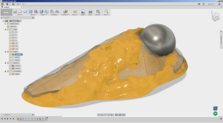
Fusion 360 mesh import

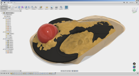
Importing into Fusion 360 is as trivial as ‘Insert Mesh’ and I had a rough 3D model within 15 minutes that ‘almost’ matched the shape of the imported mesh.  The trick here in this process is to either make the solid being worked with translucent (50% opacity for example) or the imported mesh to be translucent.  This lets you see how close you are with your featured 3D model with your target shape.  The picture above shows the imported mesh after being imported in ‘low quality’ and a grey solid modelled using simple features.  I dislike sculpting even for this application, and you can see in the feature tree above I had only used so far one extrude, one revolve, and two each of fillets and chamfers for this model (the other revolve is the ball, which technically isn’t part of the what I need).

A couple of extra views, mesh hidden and added ‘pinky pad’

Validating the shape…

This is where I go ‘oopsies’ and realised that part of my workflow does include the use of special equipment, an Up! Box 3D printer… again not an ad, but tell the guy Madox sent ya 😉

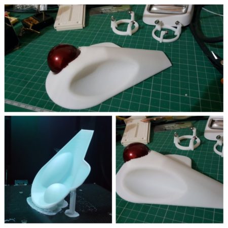
I suppose I could argue the prototype design was complete prior to this step, but having something you can put in your hand to validate is very very nice.  Having the physical print (with yet a different donor trackball) to try with my hand made me go ‘meh…this isn’t right…’, that huge mismatch with the mesh should have told me something!

Wait… I used special equipment 😛

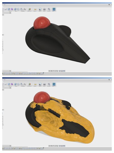
I quickly remodelled the casing and printed it again…yet I still didn’t see the obvious ‘ITS NOT MATCHING THE MESH MATE!’ glaring at me in the screenshot below.

Mistake #2…

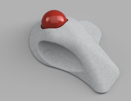
Render of mistake #2, looks disturbingly like an existing commercial product….

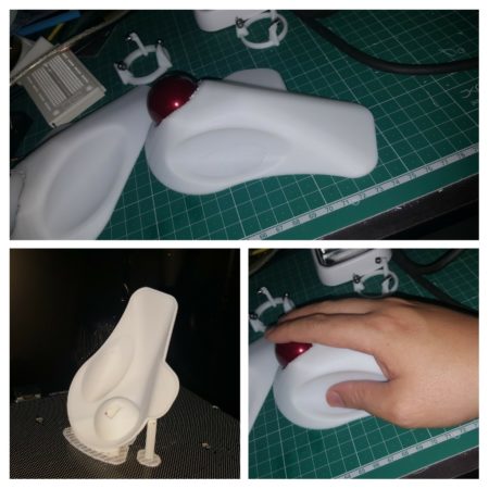
Print and hand trial of mistake #2, nope, the thumb position really felt off.

Third time lucky… and on-screen validation

While printing doesn’t cost much, printing two ‘not quite right’ casings was annoying me.  Yes that is the point of having a 3D printer, to make mistakes more quickly, but it doesn’t mean I have to like making them.

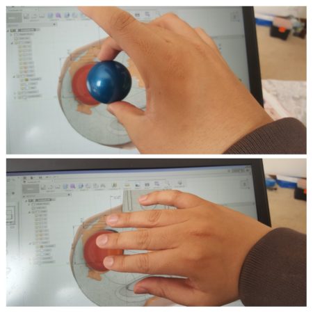
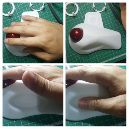
Then it occurred to me that I could check rough positioning of button placements etc on the screen!  A donor 40 mm Kensington trackball was borrowed to calibrate the on-screen display of the CAD model, and I simply placed my hand on the screen to get a rough appreciation that I’ve finally got the buttons in the right place.

Checking it before printing! On the screen!

Final fitting…Its alive!!! … or at least it fits.

The final fitting confirms the form, shape and placement of the buttons.  Yay… now I just have to wait for the electronics to arrive in the mail and onto the next step.  Less 3D printing time, uploading and cloud processing time, the actual design effort took roughly an hour and demonstrates how easily a simple child’s toy can be used in an engineering context.

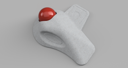
Final pre-electronics tweaking render

Once I get the electronics, there will probably be more tweaking to be done to the model to fit the items inside but I consider the physical form to be ‘almost complete’ for now.  The observative amongst you would have noticed the new ‘wing’ in the final render where my little finger is… let’s just say I’m prone to scope creeping my projects… *cough it might be provision for a 3D gesture controller*

If there is interest, I’ll write up on the electronics design too…

Tiertime Up Box 3D Printer – Short Review

Opening excuse

One of my new year resolutions was to post more here, but with a new child, sick kids, computer continually eating my homework, dying phones eating my home work, it hasn’t really worked out.  Well that’s my excuses out of the way…

Background

I’ve been a happy Up Plus! 3D printer user for several years, convincing probably around 20+ people I know to get one.  However with the concern of particle emissions from 3D printers and a new-born child in 2013, I decided to err on the paranoid side and off-loaded my printer to someone else.

The relapse

Though an engineer always has an itch to scratch wanting to make gadgets and stuff so… unashamedly (or slightly ashamed) I got myself another 3D printer (and a Thermomix… but that’s another story).

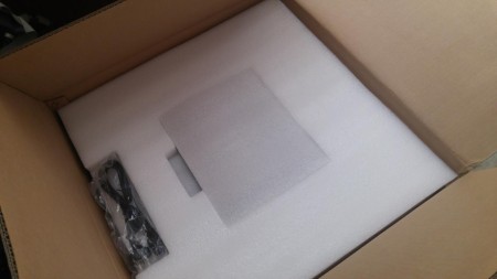
Up Box in Packaging
Up Box in Packaging

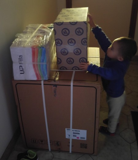
The Tiertime Up Box 3D Printer arrived just over the new year break for me to get my grubby little hands on it.  The size of the ‘box’ it came in could have easily accommodated 4 small children and I hit my first hurdle as soon as I tried opening the box, it needs two adults to unpack…

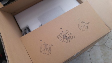
Argh it needs 2 people

What’s inside the box…

Inside the box is a very professional set of packaging, protecting the contents.  Like the previous Up! printers, there is almost no assembly involved and everything is almost good to go out of the box.

Well that's nicely packed
Well that’s nicely packed

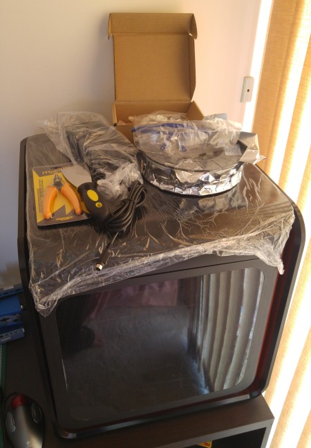
Behind all the styrofoam are contents similar to the original Up Plus and Up Mini.  The photo below shows all the contents laid out on top of the printer.  From a tools perspective, the very handy side cutters are still there with the very sharp spatula/scrapper thing.  For safety, protective eye-wear is provided being a nice touch to protect your eyes from flying plastic when you’re removing support.  The heavy gloves are no longer provided, but honestly I’ve never really  used them.

The Up Box, Box Contents

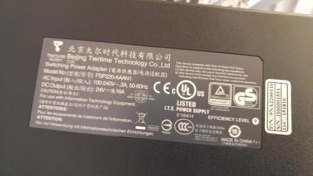
An USB cable is provided to connect to the computer as well as power cords and the power supply.  Whereas the previous Up Plus and Up Mini printers used heavy duty Hewlett Packard laptop power suppliers, the Up Box appears to come with a branded power supply.  Looking at the output (24V × 9.16A = 220W!!!), it probably is a case of out-growing the available off-the-shelf supplies.

Up Box Power Supply
Up Box Power Supply

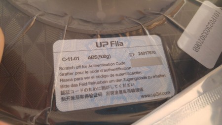
The Up Box comes with a roll of filament so you can rock and start printing ASAP.  I’m not sure who in their marketing department thought ‘Fila’ was a good idea, it sounds too much like the shoe brand and just confuses people I think.  The Up ‘Fila’ment I’ve always found to be superior to most others you can buy, and the Up printers are tuned to work particularly well with it so I’ve gone ahead and bought 10 rolls…

The filament size has been downgraded from 700g to 500g, an odd choice considering the larger print area/volume of the Up Box.  What were they thinking?

The 'Fila'... errr
The ‘Fila’… errr

What’s in the Box within the box…

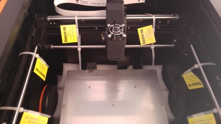
Everything inside is almost ready to go with nothing to assemble.  There are however a whole bunch of cable ties, used to prevent the platform from rattling during transport, that needs to be snipped off.  Luckily these are professionally labelled ‘Remove Me – Please remove me.  I am shipping clip’.  OK the last bit reads a bit funny, but you have to admit its kind of nice.

Secured for transport

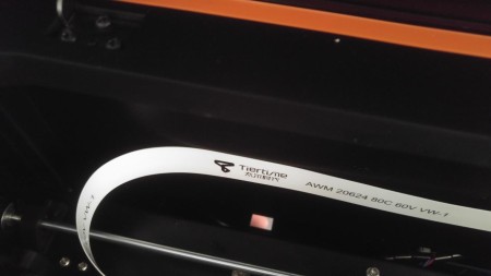
The internal build of the printer is nice a clean, with a two tone scheme (black and orange) consistent throughout.  In the photo above, you can see the HEPA filter on the left.  Below you will notice even the cable assemblies are professional labelled and branded giving the printer just a little bit more of the up-market feel (er…excuse the pun, definitely not intended).

Branded cables...Oooo pretty...
Branded cables…Oooo pretty…

The printer also comes with 4 print plates, 3 perforated much like those PCB type ones provided on the Up Plus and Mini as well as 1 smooth bed one presumably for PLA usage.  The additional plates are handy and allows you to swap them out and continue printing without downtime.  The plates I received unfortunately weren’t very consistent and a couple of them was very warped, putting them through a couple of print/heat cycles relieved the issue but clipping them on the first time proved tricky.

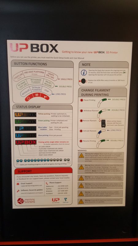
The underside of the lid conveniently has a quick start guide with instructions on use which I thought was a nice touch.

Handy instruction sheet

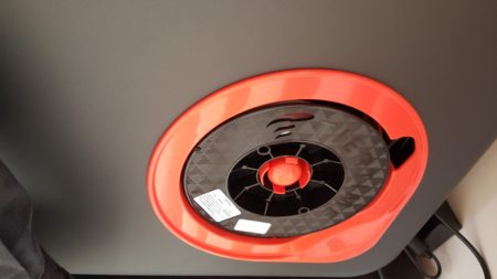
The side of the printer contains a fancy spool holder with magnetic clip, it does look pretty I have to admit.

Filament goes here...
Filament goes here…

Unfortunately, the only thing going for it is ‘pretty’ as the filament spool size is truly underwhelming at 500g.  I am not looking forward to swapping filaments in-between large prints, but for those who do multiple small prints this shouldn’t be an issue.

Undersized filament spool

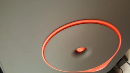
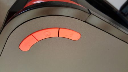
The top right of the box holds 3 multi-function buttons depending on how long you press them.  Functions available include pre-heat, re-print last job, withdraw and extrude filament, pause/resume/stop, and my favorite lights on.  The Up Mini 2 appears to contain a LCD screen, but to me that’s feature bloat, three buttons seems to do everything I think I’ll need.

Control buttons
Control buttons

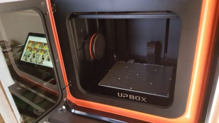
The Up Box has a limit switch on its front door to pause printing whenever it is opened.  I think it is intended as a safety feature, but the feature is not included on the top lid presumably assuming kids aren’t that tall.  The picture below shows the Box with the front door open and the ABS build plate installed, I really appreciate the professional appearance of the whole set-up.

The Box...
The Box…

Printing

The Up Box prints slightly quieter than the Up Plus, probably due to its construction.  There is no noticeable improvement on the quality of the prints to its predecessor, but they were pretty damn good already.  Probably the one true reason to upgrade to the Up Box if you’ve already have an Up Plus would be for the significantly larger print volume and the ability to print bigger parts without warping.

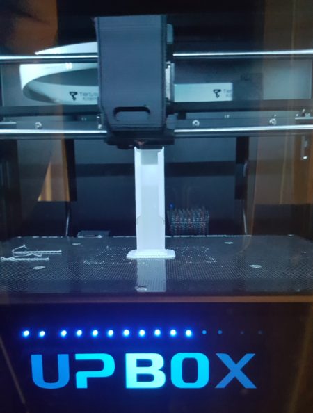
One nice improvement over the Up Mini is that the front window is now much more transparent and with the LED lighting within lets you see the print rather well.  The photo below was taken through the front window, it is still rather reflective but you can see everything going on inside well and removes that ‘has my print screwed up’ angst that I had when I was trying to use the Up Mini.

Printing in action
Printing in action

A word of warning though, the bed auto-leveling and height adjustment should be verified!  Do not rely on it!  Or pre-heat your bed before doing the adjustments.  I had a series of bad prints initially but sorted it out after manual adjustments, the variation to the initial auto adjustment values and my own manual adjustment values were very far off.  It has been smooth printing every since.

Some random prints I’ve done

With reference to my opening excuse, I haven’t had much time to do much 3D printing (in fact I wrote that excuse a week ago, I’ve been sick since!), so I’ve only got a couple of examples of what I’ve printed with the Box.  The support pulls off nicely and all is good 🙂

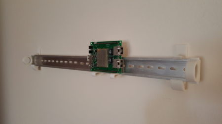
Random DIN Rail Mount Print :)
Random DIN Rail Mount Print 🙂

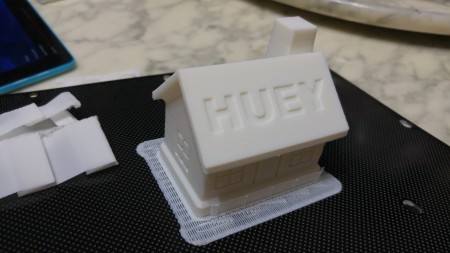
Huey House
Huey House

Should you buy it? (Short Answer)

Short answer – Yes, but you should use this link – Up Box 3D Printer.

Should you buy it? (Longer Answers)

Yes – Professionals, hobbyists and business use

Yes if you need to print functional items and don’t want the hassle of tuning/tweaking/fault finding or any of the myriad of problems associated with cheap 3D printers and 3D printer kits.  The higher price is well worth the time and frustration saved if you’re planning on using it for personal projects, and definitely worth the investment if you’re buying it from a company perspective (plus its an expense, its a deduction!).

Maybe – Schools, parents

If you’re a school or educational institution, you may get more bang for your buck with the Up Mini or the upcoming Up Mini 2.  Having more printers per student outweighs the large print volume the Up Box brings in my opinion.

If you’re a parent thinking the HEPA filter will let you print in piece, then chalk it down as a maybe.  There are so many holes and crevices I’m not sure the HEPA filter does much.  You should consider getting a carbon activated filter unit to remove the smell and definitely print in a separate well ventilated room away from your children.  I am not an expert but I consider 3D printer emissions in the same category as smoke, i.e. increases SIDS risks.  Can’t be certain but caution is good.

No – People learning on building or on a tight budget

If you’re a hobbyist/student and building the printer is part of the learning experience.  Personally, I think many of the kits out there will set you for disappointment.  Do some research and don’t simply go for the cheapest.

The almost $3000 price tag may place it out of reach for many people.  Instead of buying a cheap 3D printer kit, I suggest to you to look into services such as Shapeways.  They offer an excellent service and for several prints a year, they’re cheaper than owning a 3D printer.

The people who sell the Tiertime Up printers in Australia also have a 3D printing service locally, I think it is http://3dprint-au.com/ but I’ve not tried it out yet…


Carambola 2 Images


carambola2


Yippee, I finally received a batch of Carambola2s in the mail today.  I had a couple that were ready for me to pick up a couple of weeks ago but didn’t get it until Saturday…

So similar to the TL-WR703N I’ve prepared a standard image with most of the hacker stuff baked in for people to try out with a limited repository (not as comprehensive as the TL-WR703N one and definitely not compared to the 8devices/OpenWrt ones) compiled and available online.

I’ve also build the Image Builder again for people to remix and make their own images without doing the full OpenWrt build.

The following have been tried and seem to work :

  • Python
  • Python-libusb1
  • Pyserial
  • Python HTTP Server
  • USB Serial (ACM)
  • WiFi, Eth0, Eth1, Buttons
  • USBIP

Don’t expect anything not to work, but it was worth noting 🙂

Someone really should donate me a 3G modem to test with…

May Day Uploads – TL-WR703N, TL-WR720N & TL-MR3020 images + Secret Sauce

Uploaded a bunch of images for the TL-WR703N, TL-WR720N & TL-MR3020 on May 1st.

Based on OpenWRT r36503, it has the new 3.8.10 kernel as well as the new LuCi theme.  Due to the slowly expanding size of the kernel and the packages, I had to drop 3G out from the ‘standard’ image and made a separate ‘3G’ image.  All images are very barely tested though so that’s why I’m not updating into the main project page.

The benefit of these images is that this time I’ve included the image builder as well as helper scripts that should give people an idea on how to quickly roll their own images and still have access to a set of online packages.

Lots of comments asking me how I compile USBIP and make it work with the outdated Windows client, so I’ve included all the extra files I use on-top of the OpenWRT source in a package.  Yup I was too lazy to set up a github or similar for it 😛  It basically is 3 packages and a couple of modified source files…

All files located here :-
http://code.google.com/p/madox/downloads/list

TP-Link TL-WR720N Test Images (OpenWRT)

I’ve uploaded two test images based on OpenWRT r35905 (Linux 3.8.2) for the TL-WR720N here :-

http://code.google.com/p/madox/downloads/detail?name=openwrt_tl-wr720n_standard_2013-03-09.7z

http://code.google.com/p/madox/downloads/detail?name=openwrt_tl-wr720n_base_2013-03-09.7z

Both Ethernet and WiFi appear to work as well as the mode switch.  Both images are similar to the WR703N images but with less things (mjpg-streamer ser2net dropped).  I had to cut down as it appears the newer kernel is significantly larger [either that or I did something wrong].

I will upload the repository and packages tomorrow if I don’t find a better way to squeeze more goodies in.

How to install OpenWRT on a TL-WR703N that came with DD-WRT

USE THESE INSTRUCTIONS AT YOUR OWN RISK

I have only done this procedure once and sharing because of the lack of information on the web on how to do this.

Some of the sellers of the TL-WR703N are shipping the routers with DD-WRT pre-installed – some with a Chinese interface, some with an English interface.

Regardless, you need telnet or SSH access to the router as upgrading via the web interface will not work.

Step 1 :

Get the OpenWRT image onto the router.
e.g.

root@DD-WRT:/tmp# wget http://192.168.1.142/openwrt/ar71xx/openwrt-ar71xx-generic-tl-wr703n-v1-squashfs-factory.bin
Connecting to 192.168.1.142 (192.168.1.142:80)
openwrt-ar71xx-gener 100% |*******************************| 3840k 0:00:00 ETA

Other methods can be found here :- http://wiki.openwrt.org/doc/howto/generic.sysupgrade

Step 2 :

The TRICK is that the partition names are different between OpenWRT and DD-WRT.  Whereas all OpenWRT instructions will tell you to write to the ‘firmware‘ partition, this does not exist on DD-WRT and you have to use the ‘linux‘ partition instead.  Use the ‘mtd’ command as per the example below to write the OpenWRT image onto the router.  Note the ‘-r’ argument will reboot the router as soon as the flash is complete.  (As usual, do not power off or disconnect during the flashing!).

root@DD-WRT:/tmp# mtd -r write openwrt-ar71xx-generic-tl-wr703n-v1-squashfs-factory.bin linux
Unlocking linux ...
Writing from openwrt-ar71xx-generic-tl-wr703n-v1-squashfs-factory.bin to linux ... [e]
Connection closed by foreign host.

TL-WR703N Example Project 4 : Webcam Streaming

Connecting a webcam and using the router to stream video around the place should be one of the easiest things to do. A bit too easy in that I neglected to provide simple instructions on how to set it up.

mjpg-streamer and the necessary drivers are included in the standard images I provide on the TP-Link TL-WR703N project page.

Preliminary steps :-

  1. Get a router, load it with the standard image.
  2. Set-up wireless or any other networking changes.  See an example here.
  3. Plug in the camera

Now there are two ways to get mjpg-streamer to auto-start, there is an easy way and an elegant way.

  • Easy way : Just add the command to the auto start script using LuCi…
  • Elegant way : Edit the configuration files /etc/init.d/mjpg-streamer and /etc/config/mjpg-streamer

I prefer the easy way you are less likely to screw it up.  First we should check that the camera works well with mjpg-streamer…

  1. Telnet/SSH into the router
  2. Run the following command :

    mjpg_streamer -i “./input_uvc.so -n -r VGA -f 6 -d /dev/video0” -o “./output_http.so -p 8080 -n”

    This command uses VGA (640×480) resolution “-r VGA” at 6 frames per second “-f 6”.

  3. If that doesn’t work and an error appears, it most likely means your camera doesn’t support JPEG images.  If so, try the following command instead :

    mjpg_streamer -i “./input_uvc.so -n -q 60 -r QVGA -f 6 -d /dev/video0” -o “./output_http.so -p 8080 -n”

    This command forces mjpg-streamer to convert into raw into JPEG at (-q) quality 60, at resolution (-r) QVGA, this can be “160×120” for example.  The frame rate is specified by the -f (6).  This method is MUUUUUUUUCH more CPU intensive and you might have to tweak the resolution and frame rate down.

  4. Using a device connected to the router, use a web browser (e.g. Chrome) to connect to the following to get a live view:

    http://192.168.1.1:8080/?action=stream

    You can also get a single snapshot at:

     http://192.168.1.1:8080/?action=snapshot

  5. If you need to play around with the commands, use CTRL-C to kill mjpg-streamer and try again.  Avoid high resolutions (e.g. 1920×1080) as that will just crash the router.  I used 640×480 at 25 frames per second relatively happily on a JPEG enabled camera (e.g. Logitech/Microsoft ones, not the cheap no brand ones).
  6. Once you have a workable set-up, copy the command you have and put it into the local start-up.  Append the command line with an ampersand “&” so it runs in the background.  e.g.

    mjpg_streamer -i “./input_uvc.so -n -r VGA -f 6 -d /dev/video0” -o “./output_http.so -p 8080 -n” &

    Hint – In Luci, select the Systems tab, then select Startup, scroll down to the Local Startup section and add your command to the box and press save and apply.

Enjoy? 🙂